Wednesday, December 30, 2009

Diaphragm Walls (U.S. Slurry Walls)

The continuous diaphragm wall (also referred to as slurry wall in the US) is a structure formed and cast in a slurry trench (Xanthakos, 1994). The trench excavation is initially supported by either bentonite or polymer based slurries that prevents soil incursions into the excavated trench. The term "diaphragm walls" refers to the final condition when the slurry is replaced by tremied concrete that acts as a structural system either for temporary excavation support or as part of the permanent structure. This construction sequence is illustrated in Figure 1.The term slurry wall is also applied to walls that are used as flow barriers (mainly in waste containment), by providing a low permeability barrier to contaminant transport.

Slurry Wall Equipment

Slurry wall technology hinges on specialized equipment for excavating slurry trenches. The simplest type of trenching equipment is the mechanical clamshell attached on a kelly bar. Individual contractors have developed their own specialized trenching equipment like hydraulic clamshells, fraise or hydromills (sample manufacturers: Icos, Bauer, Casagrande, Case Foundation, Rodio etc). Figure 2 shows selected pictures from construction of a new subway in Boston (MBTA South Boston Transit way) including two slurry wall construction machines..

Slurry Wall History
The first diaphragm walls were tested in 1948 and the first full scale slurry wall was built by Icos in Italy in 1950 (Puller, 1996) with bentonite slurry support as a cut-off wall. Icos constructed the first structural slurry wall in the late 1950s for the Milan Metro (Puller, 1996). Slurry walls were introduced in the US in the mid 1960s by European contractors. The first application in the US was in New York City [1962] for a 7m diameter by 24m deep shaft (Tamaro, 1990), that was followed by the Bank of California in San Francisco (Clough and Buchignani, 1980), the CNA building in Chicago (Cunningham and Fernandez, 1972), and the World Trade Center in New York (Kapp, 1969, Saxena, 1974). The majority of diaphragm wall projects in the US are located in six cities Boston, Chicago, Washington DC, San Francisco and New York.

Diaphragm walls are extensively used in the Central Artery/Tunnel project (CA/T) in Boston, Massachusetts (Fig. 3). Work in the CA/T involves many cut and cover tunnels constructed under the existing artery. Some of the deepest T- slurry walls, extending 120' below the surface have been constructed for the Central Artery (Lambrechts et al., 1998).

Diaphragm (Structural) Wall Applications
Earth retention walls for deep excavations, basements, and tunnels.
High capacity vertical foundation elements.
Retaining wall-foundations
Retaining wall-water control
Used in top-down construction method as permanent basement walls

Slurry Wall for Cut-Off Wall Applications
Water and seepage control for deep excavations
Cut-off curtains
Contaminated groundwater / seepage control
Gas barriers for landfills

LIMITATIONS OF SLURRY WALLS
Slurry wall construction requires the use of heavy construction equipment that requires reasonable headroom, site area, and considerable mobilization costs. In limited headroom conditions smaller cranes can be used and the technique can be altered to “remote backfill mixing”, where the excavated soil is transported and mixed to a remote location, and then is returned as backfill.

Cement-bentonite slurry walls also provide another alternative. In this method, the trenches are excavated under a slurry that later solidifies and create the permanent barrier/backfill.

Also, one should check that used bentonite slurry and soil-bentonite slurries are able to withstand chemical attacks from the insitu soils. In such a case, alternate slurry materials such as attapulgite and treated bentonites can be used. Other backfill compositions may be used when deemed appropriate (soil-attapulgite and soil-bentonite with geomembrane inserts). When required, cement-bentonite and soil-cement-bentonite can provide greater strengths.

SLURRY WALL COSTS
Slurry wall construction cost for cut-off barries is considerably cheeper than diaphragm wall construction for deep excavations. The differences arise mainly from construction method differences. In cut-off walls construction is much quicker as a continuous trench is excavated and backfilled and reinforcement cages are seldomly used. In contrast, in diaphragm walls the wall perimeter is constructed panel by panel and reinforcement cages are almost always used.


Figure 1: Typical construction sequence of slurry walls : (A) Trenching under slurry, (B) End stop inserted (steel tube or other), (C) Reinforcement cage lowered into the slurry-filled trench, (D) Concreting by tremie pipes.


Figure 2: Diaphragm Wall Trenching equipment, (A) Mechanical clamshell in front and hydraulic clamshell in the back, (B) Smaller size mechanical clamshell


Soil Mix Walls


Various methods of soil mixing, mechanical, hydraulic, with and without air, and combinations of both types have been used widely in Japan for about 20 years. Soil mixing has been used for many temporary and permanent deep excavation projects including the Central Artery project in Boston. Known methods include as Jet Grouting, Soil Mixing, Cement Deep Mixing (CDM), Soil Mixed Wall (SMW), Geo-Jet, Deep Soil Mixing, (DSM), Hydra-Mech, Dry Jet Mixing (DJM), and Lime Columns. Each of these methods aims at finding the most efficient and economical method to mix cement (or in some cases fly ash or lime) with soil and transform soil to become more like a soft rock.
Mechanical soil mixing is performed using single or multiple shafts of augers and mixing paddles. The auger is slowly rotated into the ground, typically at 10-20 rpm, and advanced at 2 to 5 ft (0.5 to 1.5 m) per minute.

Cement slurry is pumped through the hollow stem of the shaft(s) feeding out at the tip of the auger as the auger advances. Mixing paddles are arrayed along the shaft above the auger to provide mixing and blending of the slurry and soil. Slurry lubricates the tool and assists in the breaking up of the soil into smaller pieces. Spoils come to the surface since fluid volume is being introduced into the ground. These spoils comprise cement slurry and soil particles with similar cement content as what remains in the ground. After final depth is reached, the tools remain on the bottom of the hole, rotating for about 0.5 to 2 minutes for complete mixing. At this point, the tools are raised while continuing to pump slurry at a reduced rate. Withdrawal is typically at twice the speed of penetration, 4 ft to 10 ft (1 m to 3m) per minute.

Steel beams are typically inserted in the fresh mix to provide reinforcement for structural reasons. A continuous soil mix wall is constructed by overlapping adjacent soil mix elements. Soil mix sections are constructed in an alternating sequence with primary elements are formed first and secondary elements following once the first have gained sufficient strength.
The soil mix method can be very effective at providing very stiff and waterproof retaining systems. However, it is rather limited to medium and large-scale projects because of high mobilization costs. Insufficient mix strength may result when mixing organic soils unless a high replacement ratio is maintained. Other issues include difficulties in maintaining consistent compressive strengths throughout the section of a soil mix wall.


Secant Pile Walls and Tagent Pile Wall


Secant pile walls are formed by constructing intersecting reinforced concrete piles. The piles are reinforced with either steel rebar or with steel beams and are constructed by either drilling under mud or augering. Primary piles are installed first with secondary piles constructed in between primary piles once the latter gain sufficient strength. Pile overlap is typically in the order of 3 inches (8 cm). In a tangent pile wall, there is no pile overlap as the piles are constructed flush to each other. The main advantages of secant or tangent pile walls are:
1. Increased construction alignment flexibility.
2. Increased wall stiffness compared to sheet piles.
3. Can be installed in difficult ground (cobbles/boulders).
4. Less noisy construction.
The main disadvantages of secant pile walls are:
1. Verticality tolerances may be hard to achieve for deep piles.
2. Total waterproofing is very difficult to obtain in joints.
3. Increased cost compared to sheet pile walls.

Secant pile wall design when steel beams are used involves the use of weaker than normal concrete. The pile that is lagging the wall between two main beams has to be examined for shear and compression arching.


Secant pile walls can be used for temporary support of deep excavations or to form permanent earth retention systems. They can also serve the dual function of excavation support during construction and as part of the permanent foundation system. Since secant pile installation creates minimal disturbance, this technique is suited for dense, urban environments. Walls are constructed by the sequenced construction of overlapping, reinforced concrete piles installed in a top-down process by either drilling or augering methods.  Although more costly than sheeted excavation support, this system offers greater alignment flexibility and increased wall stiffness and can be installed through bouldery or cobbly soils.


Secant pile wall construction is the most economical method of creating an effective water control barrier for dam remediation. Drilling techniques are used to construct overlapping concrete elements through rock, extending below the water seepage elevation. Sequenced drilling and concreting of the individual elements that make up the finished barrier allows the concrete to cure, ensuring a tight seal between elements for complete water cut off. Secant Pile Walls can be constructed to depths of 120 ft.


More Information on Basement & Slope Retention
Contiguous pile wall - typical diameters and spacing


Diameter
mm
Spacing
mm

350
450
600
750


400
600
750
900

Secondary hard/soft secant pile wall - typical diameters and spacing


Diameter
mm
Spacing
mm
Primary
Secondary


450
600
750


450
600
750

600
900
1000
 Note:  The gap between the primary or structural piles should not exceed 40% of the diameter of the soft piles


Typical applications of embedded retaining walls
(ICE Specification for Piling and Embedded Retaining Walls)


Wall Type
Typical height range
Groundwater control
Typical vertically
Cantilever
Propped
Temp.
Perm.
Sheet pile wall
To 5m
4 - 15m
Yes
No
1:75
Combination wall
To 10m
5 - 20m
Yes
No
n/a
King post
To 4m
4 - 20m
No
No
n/a
Contiguous
To 5m
4 - 20m
No
No
1:75
Hard/soft secant
To 5m
4 - 20m1
Yes2
No
1:75
Hard/hard secant
To 6m
4 - 25m
Yes
Yes
1:200
Diaphragm wall
To 8m
5 - 30m
Yes
Yes
1:75

Notes:
1.  The depth to which hard/soft pile walls can provide water resistance is restricted by 
     the construction tolerances of the boring rig and the groundwater pressure to be
     resisted.  This type of wall is most commonly used to resist groundwater flow to
     maximum depths of approximately 6m.

2.  The long term resistance of the soft elements of hard/soft secant pile walls to
     groundwater flow has not been proven and will vary according to the soft mix design. 
     It is recommended that long term water resistance is provided for by additional works
     such as reinforced concrete lining walls which transfer the groundwater load into the
     hard elements.


Tangent Pile Wall


Tangent pile walls are a variation of secant pile walls and soldier pile walls. However, tangent pile walls are constructed with no overlap and ideally one pile touches the other. Compared to secant pile walls, tangent pile walls offer the following advantages:
1. Increased construction alignment flexibility.
2. Easier and quicker construction.


The main disadvantages of tangent pile walls are:
1. They are can not be used in high groundwater tables without dewatering.
2. Each pile is independent from adjacent piles


Vertical Wood Sheeting


Vertical wood sheeting can be installed on projects where access is limited or where surrounding conditions are too sensitive for heavy equipment. 


Diagonal (raker) braces combined with horizontal wales and heel blocks provide support for wood sheeting, usually installed by hand, one board at a time.

When soil conditions indicate trench face sloughing or raveling, approved wood sheeting may be used in conjunction with the vertical shores.


Steel Sheetpilling


Interlocking steel sheetpiling
can be used to advantage:
  • when excavating into water-bearing soils.
  • when excavating into contaminated soils.
  • when sheeting is to be removed after backfilling is complete
  • when sheeting is to remain permanently exposed.


Careful consideration of the method of sheetpile installation is necessary.

Vibratory hammers are most commonly used. However, reconsolidation of vibrated soils can cause settlements adjacent to the sheetpile installation. Damaging vibrations can travel through soil to affect buildings and utility structures, sometimes with disastrous results. 
Sheetpiles can be advanced using impact pile driving hammers which shear the soil, instead of vibrate the soil, causing less damage to adjacent structures.


Sheet pile walls are constructed by driving prefabricated sections into the ground. Soil conditions may allow for the sections to be vibrated into ground instead of it being hammer driven. The full wall is formed by connecting the joints of adjacent sheet pile sections in sequential installation. Sheet pile walls provide structural resistance by utilizing the full section. Steel sheet piles are most commonly used in deep excavations, although reinforced concrete sheet piles have also being used successfully.
Steel sheet piling is the most common because of several advantages over other materials:
1. Provides high resistance to driving stresses.
2. Light weight
3. Can be reused on several projects.
4. Long service life above or below water with modest protection.
5. Easy to adapt the pile length by either welding or bolting
6. Joints are less apt to deform during driving.


Sheet pile walls are constructed by:
1. Laying out a sequence of sheet pile sections, and ensuring that sheet piles will interlock.
2. Driving (or vibrating) the individual sheet piles to the desired depth.
3. Driving the second sheet pile with the interlocks between the first sheet pile and second "locked"
4. Repeating steps 2 & 3 until the wall perimeter is completed
5. Use connector elements when more complex shapes are used.


Sheet pile wall disadvantages are:
1. Sections can rarely be used as part of the permanent structure.
2. Installation of sheet piles is difficult in soils with boulders or cobbles. In such cases, the desired wall depths may not be reached.
3. Excavation shapes are dictated by the sheet pile section and interlocking elements.
4. Sheet pile driving may cause neighborhood distrurbace
5. Settlements in adjacent properties may take place due to installation vibrations

Soldier Beams and Timber Lagging

Soldier pile and lagging walls are some of the oldest forms of retaining systems used in deep excavations. These walls have successfully being used since the late 18th century in metropolitan cities like New York, Berlin, and London. The method is also commonly known as the "Berlin Wall" when steel piles and timber lagging is used. Alternatively, caissons, circular pipes, or concrete piles can also be used as soldier piles but at an increased cost. Timber lagging is typically used although reinforced concrete panels can be also utilized for permanent conditions. Soldier pile walls are formed by:

1. Constructing soldier piles at regular intervals (6 ft to 12 ft, typical)
2. Excavating in small stages and installing lagging.
3. Backfilling and compacting the void space behind the lagging.

Moment resistance in soldier pile and lagging walls is provided solely by the soldier piles. Passive soil resistance is obtained by embedding the soldier piles beneath the excavation grade. The lagging bridges and retains soil across piles and transfers the lateral load to the soldier pile system.


Shallow excavations can be supported using cantilevered steel soldier beams with timber lagging boards installed between them as the excavation progresses. Soldier beams can be driven with conventional pile driving equipment or installed vibration free as shown.

Soldier beams and timber lagging in many cases will be the most economical choice for support of excavation.


Deeper excavations will require internally braced soldier beams to prevent excessive movements of the sheeting system and corresponding settlement of the soils behind the sheeting. Diagonal (raker) braces carry loads from the soldier beams to heel blocks below final excavation levels.


Tieback anchors
can replace internal braces to provide an excavation free of obstructions. Tiebacks are constructed by drilling a small diameter shaft into the ground behind the sheeting system. Steel tendons are inserted into the shaft. Grout is pumped into the shaft to anchor the tendons as the drill casing is retracted. Hydraulic jacks lock off the tieback to the sheeting system. Multiple levels of tiebacks allow for deeper excavations.


Cross-lot/Internal Bracing - Braced Excavations

Cross-lot/Internal Bracing - Braced Excavations

Cross-lot or internal bracing transfers the lateral earth (and water pressures) between opposing walls through compressive struts. Rakers resting on a foundation mat or rock offer another internal bracing alternative. Typically the struts are either pipe or I- beam sections and are usually preloaded to provide a very stiff system. Installation of the bracing struts is done by excavating soil locally around the strut and only continuing the excavation once preloading is complete. A typical sequence of excavation in cross-lot braced excavations is shown in Figure 1. The struts rest on a series of wale beams that distribute the strut load to the diaphragm wall.

Pre-loading ensures a rigid contact between interacting members and is accomplished by inserting a hydraulic jack as each side of an individual pipe strut between the wale beam and a special jacking pblate welded to the strut (Fig. 2, Xanthakos, 1994). The strut load can either be measured with strain gages or can be estimated using equations of elasticity by measuring the increased separation between the wale and the strut. Figure 3 shows the basic arrangement for the wedging, and the telescoping preloading methods.
In some earlier projects the struts were not preloaded, and as a result when the excavation progressed deeper the soil and the wall movements were large (C1). Thus it has become standard practice to preload struts in order to minimize wall movements.

Cross-lot bracing makes sense in narrow excavations (60ft to 120ft) when tieback installation is not feasible. The struts can bend excessively under their own weight if the excavation spacing is too large. In addition, special provisions have to taken to account for thermal expansion and contraction of the struts.

The typical strut spacing is in the range of 15ft, both in the vertical and the horizontal direction. This is larger than the typical spacing when tiebacks are used, because the pre-loading levels are much higher. A clear benefit of using struts is that there are no tieback openings in the slurry wall, thus eliminating one source of leakage.


Figure 1: Typical excavation sequence in cross-lot excavations: (A) V-cut initial cantilever excavation, (B) Strut installation and pre-loading in small trenches in soil berms, (C) V-cut excavation to next level and strut installation, (B) Final grade.

Figure 2: View of cross-lot strut supported excavation with 3DEEP


Figure 3: (a) preloading arrangement, and (b) measured brace stiffness (Xanthakos, 1994)


Figure 4: Methods of preloading struts; Wedging (top), Telescoping pipe (bottom)

Figure 5 Cross-lot supported excavation NYU Medical Center, New York City

Type of Retaining Wall Failure

failure

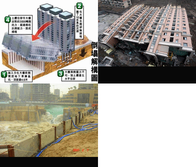
Failure in Shanghai Construction

shanghai1_
5:30am, 27 Juni 2009 Lianhuanan, distrik Minhang kota Shanghai, China.
Failure caused by Soil Excavation
id_
  1. An underground garage was being dug on the south side, to a depth of 4.6 meters
  2. The excavated dirt was being piled up on the north side, to a height of 10 meters
  3. The building experienced uneven lateral pressure from south and north
  4. This resulted in a lateral pressure of 3,000 tonnes, which was greater than why the pilings could tolerate. Thus the building toppled over in the southerly direction.

sina1
First, the apartment building was constructed
sina2
Then the plan called for an underground garage to be dug out.
The excavated soil was piled up on the other side of the building.
sina3
Heavy rains resulted in water seeping into the ground.
sina4
The building began to shift and the concrete pilings were snapped
due to the uneven lateral pressures.
sina5
The building began to tilt.
sina6
And thus came the eighth wonder of the world.

runtuh1_
runtuh2_
runtuh3_
runtuh4_
runtuh6_
runtuh8_
runtuh9_
Dampak dari pekerjaan galian tanah yang asal-asalan itu bisa luar biasa.
Agar tidak terjadi kesalahan lagi, belajarlah dari kesalahan yang pernah terjadi.

Failure in Dubai Construction


Tidak ada daya dan kekuatan selain dengan ijin Allah.
Berikut adalah urutan peristiwa kegagalan sebuah proyek kontruksi di Dubai, mungkin bisa mendapatkan pelajaran berharga dari pengalaman orang lain.

Foto 1: Dinding penahan melingkar kedap air mengalami kebocoran tipis.

Foto 2: Detail bagian yang bocor.


Suatu kejadian apapun pada struktur, jangan pernah dianggap remeh, kebocoran ini adalah tanda akan adanya bahaya, tindakan tegas dilakukan, para pekerjanya diharuskan menyingkir, dan area dikosongkan.
Foto 3: Inilah bahaya yang dimaksud.


Foto 4: Seluruh proyek musnah, tidak ada korban jiwa

Agar tidak terjadi kesalahan lagi, belajarlah dari kesalahan yang pernah terjadi. Kejujuran adalah kunci kesuksesan.

Sebarkan ke Facebook

Google Followers

Seputar Teknologi Konstruksi

TOP RANK

  • Inhibitor - *Inhibitor* merupakan zat yang menghambat atau menurunkan laju reaksi kimia. Sifat inhibitor berlawanan dengan katalis, yang mempercepat laju reaksi. *Inh...
    12 years ago